

Particular hardware related problems with a product (product must be in warranty) can be resolved by replacing parts, which customers can remove and replace by themselves. This process is called Customer Replaceable Unit or CRU. A service part, which can be removed and replaced by a customer, is called Customer Replaceable Unit (CRU) service part. Various levels of difficulty, inidicated with a specific CRU Level ID, are available and located in the service parts list.
The following is a list of the various CRU Level ID types:
| CRU Level ID 0 - | Not possible (parts, either not to be replaced by the customer or not installed in the dedicated model) |
| CRU Level ID 1 - | Possible for all customers (simple to replace parts, requiring few or no tools) |
| CRU Level ID 2 - | Possible for experienced customers (optional parts, which are slightly more difficult to replace) |
| CRU Level ID 3 - | Possible for B2B customers with helpdesk (requires trained service personnel) |
When installing a CRU, dynabook will send the CRU to you. CRU information and general replacement instructions are shipped with your product, and are available from dynabook at any time upon request.
Model specific CRU information
"Satellite Pro L40-G"
CRU service part removal and replacement procedure:
This document describes how to perform hardware service maintenance for your Personal Computer. The procedures described in this document are intended to help users to replace faulty Customer Replaceable Units (CRUs).
Removal of the Base Assy
1.) Remove nine M2.5x5.0 black Phillips head screws securing Base Enclosure
2.) Remove Base Enclosure.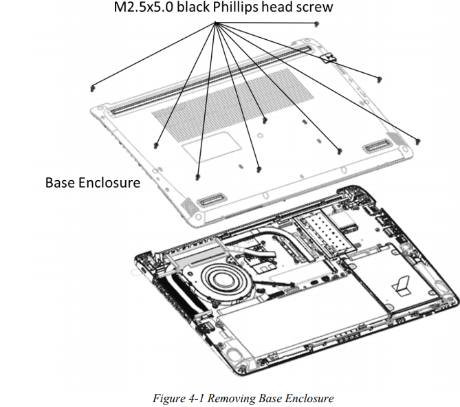
Removing Battery Pack 
1.) Disconnect Battery cable from CN6050 on system board.
2.) Remove two M2.0x4.5 black Phillips head screws securing Battery.
3.) Remove Battery. 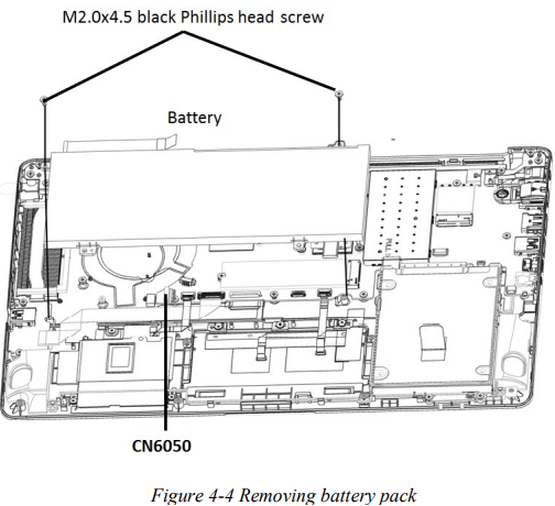

Remove Memory Module
Remove Memory Module according to the following procedures in Figure 4-2 and Figure 4-3.

1.) Pull up the Memory Module Shielding as Figure 4-2.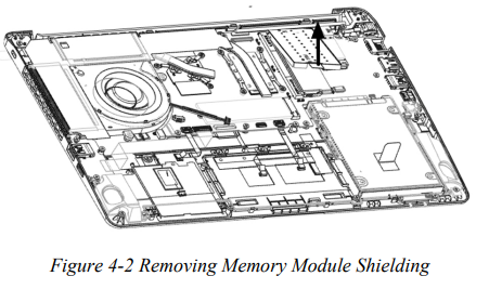
2.) Spread out the two memory lock latches so that the Memory Module pops up as
Figure 4-3. 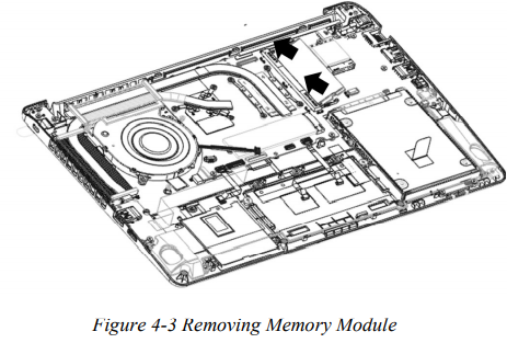
3.) Pull the Memory Module up and out at an angle, using care to avoid touching the
connectors.
Removing HDD
1.) Disconnect HDD cable from CN1700 on system board.
2.) Remove HDD pack with cable together, by pulling the tape on HDD. 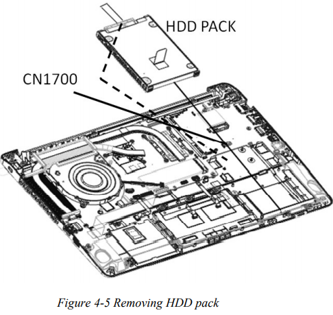

3.) Place HDD pack on flat surface (such as a desk), and release from two sides for
removing the HDD Bumper.
4.) Disconnect HDD cable from HDD.
Removing SSD 
1.) Remove one M2.0x2.5 black Phillips head screw securing the SSD.
2.) Pull SSD from CN1951 on system board. 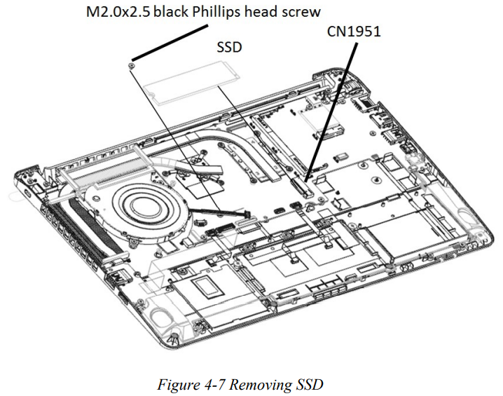
Installing SSD
1. Insert SSD into CN1951 on system board.
2. Secure it with one M2.0x2.5 black Phillips head screw. 
Installing the HDD 
1.) Insert four latches on HDD Bumper and HDD Cable to HDD pack.
2.) Place HDD pack into the correct position in the computer, holding the HDD pack by
its sides.
3.) Connect HDD cable to CN1700 on system board.
Installing Memory Module 
1.) Insert Memory Module into the connector at an angle of 45 degrees.
2.) Press down Memory Module so that it is secured with both memory lock latches.
3.) Put Memory Module Shielding back and make sure it back to the system board clip.
4.) After the computer is turned on, check the hardware configuration in the Hardware
Setup or TSETUP program to make sure that the installed Memory Module has been
recognized by the system. If it has not been recognized yet, check the connections. '
5.) If the unit only contains one pcs of Memory Module, insert it into the connector
which is near speaker.
Installing Battery Pack

1.) Take a new or recharged Battery Pack.
2.) Place Battery Pack in correct position.
3.) Secure Battery with two M2.0x4.5 black Phillips head screws.
4.) Connect Battery cable to CN6050 on system board.
Installing Base Enclosure
1.) Place Base Enclosure in correct position.
2.) Secure Base Enclosure with nine M2.5x5.0 black Phillips head screws.
Perform a functional check to see, if the unit is working as expected.
The appendices describe the following:
 NOTE
NOTE
Pictures shown are for illustration purpose only. Actual product may vary due to product enhancement or platfrom generation changes.
DISCLAIMER
Dynabook provides this information "as is" without warranty of any kind, either express or implied, including, but not limited to, the implied warranties of merchantability or fitness for a particular purpose. Dynabook shall not be responsible for the topicality, correctness, completeness or quality of the information or software provided. Dynabook is not liable for any damage caused by the use of any information or software provided, including information that is incomplete or incorrect. Any trademarks used herein belong to their respective owners.
Copyright Dynabook Europe GmbH. All rights reserved.
